Architecture · Software

State Transition Systems

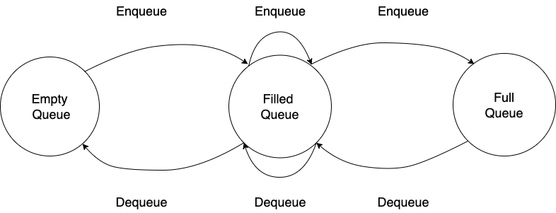
  • State. The information that a system remembers defines its state. For example, a queue system can be in a number of different “states”: an empty state, a queued state, or a full state.
  • Transition. A transition is used to describe the change of a system from one state to another. A single system state can have multiple transitions; majority of systems today will have multiple transitions branching from one system state. This makes behaviors non-deterministic, since we cannot predict what the next state of the system will be.
  • Behavior. The behavior of a system describes what the system will do when exposed to a condition, which can vary from timed system events to user input.

State transition systems can be thought of as directed graphs. Each node of the graph represents the set of states, and each edge of the graph represents the set of transition. We can determine how a system reaches a specific state by simply traversing the graph.

State TransitionsSystemDiagram.png
State transition system for a queue

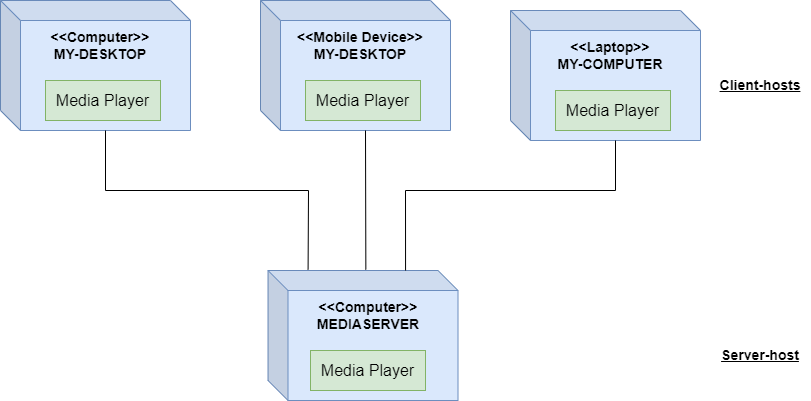
State transition systems can help us understand how parallel processing, multithreading, or distributed computing can affect the overall state of our system. Do we need to wait for another process to finish its work before continuing? At which junction of our system will we be bottlenecked?

In addition, state transition systems can help us identify deadlocks. A deadlock occurs when a process is waiting indefinitely for another to release a shared resource or complete its work. A state transition system can help you easily identify deadlocks since they occur if there is a condition that prevents a transition out of particular state.

Architecture · Software

Client Server n-Tier

Another name of the n-Tier is Multitier. Tiers often refer to components that are on different physical machines. The number of tiers varies quite a bit, 3- and 4-tier architectures are quite common, but any number is possible. So this architecture is called n-Tier or a Multitier.

The relationship between 2-Tiers in an n-Tier architecture is often a client/server relationship. The server side provides services. This could be storing information in a database, performing computation tasks, any sort of service. The client-side requests these services through messages. The communication between the two sides is called Request-Response. A tier can act as both a server and a client, simultaneously fulfilling the requests of its clients and making requests of its servers.

2-Tier Architecture (Client Tier and Data Tier):

nTierDiagram.png
2-Tier example.
Continue reading “Client Server n-Tier”
Architecture · Software

Repository-based Systems: Databases

Data-Centric Software Architecture helps to increase the maintainability, reusability, and scalability of a system. There are 2 types of components:

  1. Central Data – the component used to store and serve data across all components that connect to it.
  2. Data Accessors – the components that connect to the central data component. The data accessors make queries and transactions against the information stored in the database.
Data Accessors.png

The data accessors are separated from one another and communicate only to the central data component. The central data facilitates data sharing by saving the desired information from the current state of the system and serving data as requested.

Continue reading “Repository-based Systems: Databases”
Software

Main Program and Subroutine

Main program and subroutine is a style that is fundamentally focused on functions. When presented with a system to model, you break up the overall functionality of the system into a main program and subroutines.

In the diagram, we can see how subroutines are connected by procedure calls, and may even have nested calls:

MainProgramAndSubroutines.png

The structure of the resulting code is not flat, it’s hierarchical, hence it can be modeled as a directed graph. The subroutines, as declared in the code are structured as a big call tree. As OO languages, procedural programming supports abstract data types, but inheritance is not explicitly supported. It’s not easy to make one abstraction type an extension of another type. Here, the main consideration is the behavior of functions and how data moves through them. As a result, this approach is suitable for computation-focused systems.

Continue reading “Main Program and Subroutine”
Software

Abstract Data Types and Object-Oriented (basics)

Each programming paradigm has its own set of constructs and their use will shape the system you create.

The main OO concepts:

  1. Abstraction – simplify a concept by ignoring unimportant details.
  2. Encapsulation – allows to bundle data and functions into a self-contained object, so the other objects can interact with it through an exposed interface.
  3. Decomposition – allows you to break up a whole problem into smaller, distinct parts.
  4. Generalization – allows you to factor out conceptual commonalities.

Object-oriented refers to a system composed of objects. where each object is an instance of a class (the type of each object is its class). Objects may interact with each other through the use of their methods. The OO paradigm allows for inheritance among abstract data types (one abstract type can be declared an extension of another type).

Architecture · Software

UML Activity Diagram

In a UML activity diagram, you represent the control flow from one activity to another in software system (like a levels in video game). You can consider activities as actions that further the flow of execution in a system. They are actions, that when completed, cause another action to execute. For example these actions can alter objects or create new objects. These changes/actions drive the application forward.

The purpose of the activity diagram is to capture the dynamic behaviour of the system. The activity diagram allows you to map out the branching into alternative flows.

When creating the diagram, firstly have to identify the activities.

Activity diagram have 2 major parts, the start and end nodes:

Start and End nodes.png
The start and end nodes

The intermediate activities are shaped as a pill. They describe all of the activities that change the game state before the game ends.

Intermediate Activity.png
The intermediate activity
Continue reading “UML Activity Diagram”
Architecture · Software

UML Deployment Diagram

Software release involves:

  • Separate libraries
  • An executable.
  • An installer.
  • Configuration files.
  • Other different pieces.

To make software ready to run, need an idea of how to fully deploy all the different files to a needed environment. To visualize it, can use the UML deployment diagram. The deployment environment (deployment target) can be very specific. The details on the deployment diagram will change accordingly.

The physical result of the development process is artifact. For example artifacts for video game can include an executable, installer, audio libraries, multimedia assets.

An artifact.png
An Executable artifact.

There are 2 types of deployment diagrams:

Continue reading “UML Deployment Diagram”
Architecture · Software

UML Package Diagram

A package – groups together elements of a software that are related. This elements can be related based on Data, Classes, User Tasks.

A package also defines a namespace for the elements it contains, helps to organize the named elements of a software into a separate score. An element can be uniquely identified in the system by a fully qualified name, based on the own name and the name of the package that element is in (namespace).

Package diagram show packages and the dependencies between them. The packageable elements might be: Data, Classes, Other packages. Package diagrams are helpful for when you want a high-level look at your system, how different packages depend on each other.

A package has a simple depiction, which looks like a tabbed folder.

Package.png
A package without details.
Package with details.png
A package with details.
Continue reading “UML Package Diagram”
Software

UML Component Diagram

UML component diagrams are concerned with the components of a system. Components are defined as independent, encapsulated units of the system. Each component provides an interface for other components to interact with it.

Component Diagram.png
The Component Diagram example.

The Component Diagram are used to visualize how a system’s pieces interact and and what relationships they have among them. This is high-level diagram, and shouldn’t considered to have details.

Continue reading “UML Component Diagram”